Projects
A roughly chronological list of projects I have been a part of
NEID Spectroscopy
Human Genome Imaging/Z-stack processing
-
I built a new pipeline for processing z-stacked biological imaging generated from flourescense microscopy.
Using ML and statistical segmentation, I built a pipeline to mask flourescing features of interest,
Convert the masks to 3D pointcloud data, run marching cubes and some data cleanup like erodion/dilation,
then assemble a renderable model. Using the 3d spatial information in the masks, the features of interest
are converted to meshes that are orders of magnitude lighter than the original dataset, contain novel
connectivity data, and show only the features, without being obstructed by background structures.
These objects are easy to import to engines like Unity, which offers cutting-edge rendering libraries, or
Blender/MeshLab for lots of fun new types of analysis like connectivity coloring.
-
Link to paper
TESS ML Model
-
This was a fun project that started out as a final for a machine learning class, but I then expanded into
a perhaps moderately viable tool. The basic idea is that the TESS satellite produced a list of ~8000 exoplanet
candidate stars. The process to vet these candidates is long and labor-intensive, usually requiring significant
time on world-class observatories. This project has looked at the ~3500 (at time of writing) candidates that have
either been confirmed or denied, pulls all of the information readily available about the host stars and candidate
planets, and fits a variety of ML models to the data. I then compared their relative performance, and we can apply
the best model to the remainder of the catalogue of candidates (~4000 at time of writing.) Somewhat unexpectedly, gradient
boosting outperformed all the other methods tested. Being concerned about some low-hanging-fruit stars over-contributing
to the fit, I also ran a knn label-propegation to the entire dataset before refitting with the best tested model (XGboost.)
If you plan to use that version, it may be wise to revisit the knn propagation, either setting a confidence threshold or
iteratively propagating the labels in several cycles. The final model, test and train datasets, and complete
code base can be found on the Github page here. Suprisingly
we get pretty good results, with a nearly 90% accuracy and F1 score, 94% recall, and 85% precision. Even with the low-tech
label propagation, precision increases to 87%, and the other stats take a moderate decline of ~1-5%
Tube Adventures
-
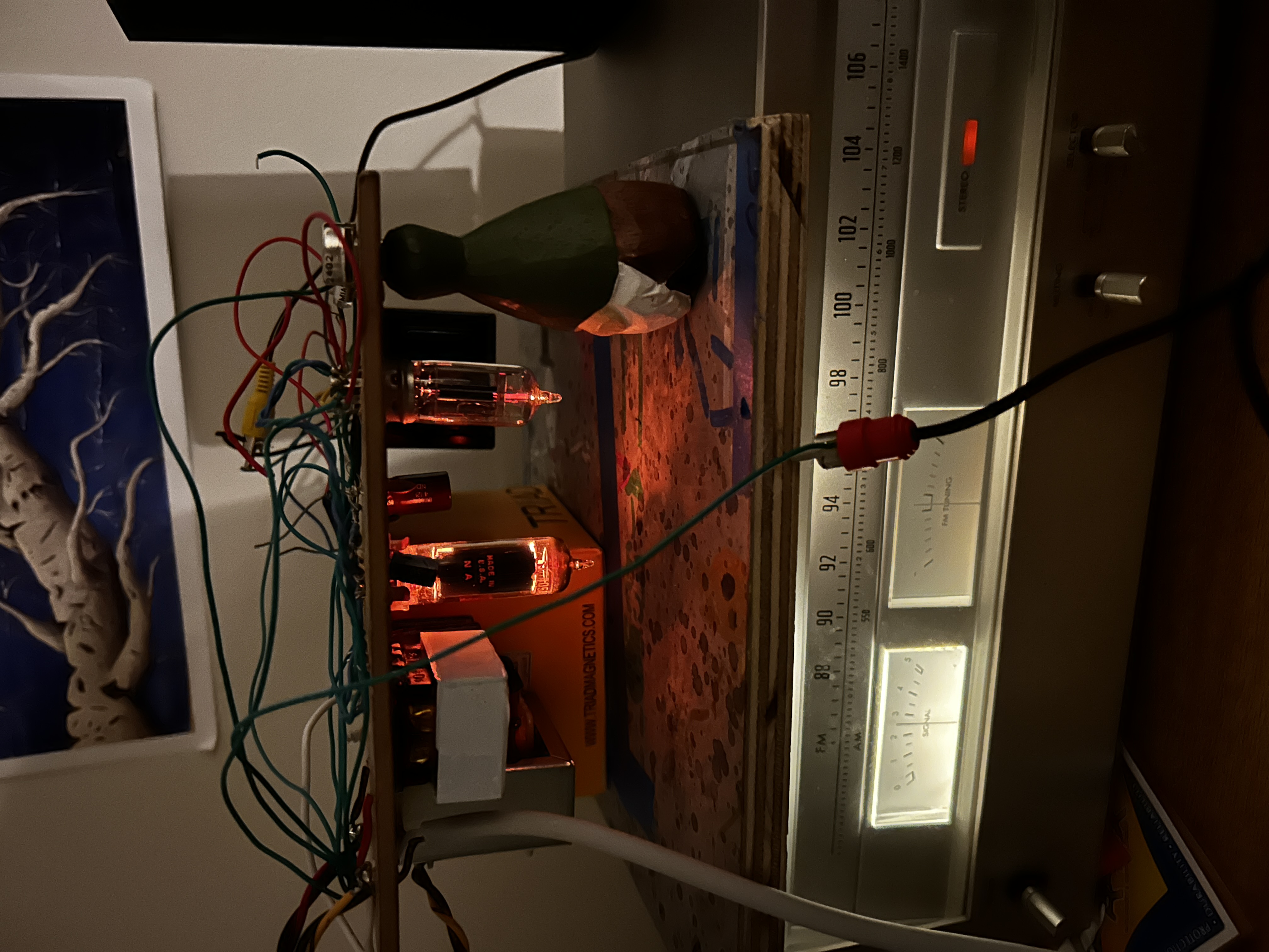
In my free time, I am nearly always building or tinkering with something. Most recently what has captured my attention are
analouge audio processing circuits, in particular, with vacuum tubes. Along this journey, I have picked up a variety of fun
tools, like ltSpice. Excuse me as I go into the technical details on my most recent builds. I will try to include enough pretty
pictures to make it worth your while.
-
First Amplifier
Starting with the most basic viable tube amp design, designed by the legendary Max Robinson, who's web page is down at
the time of writing, but may still be viewed here,
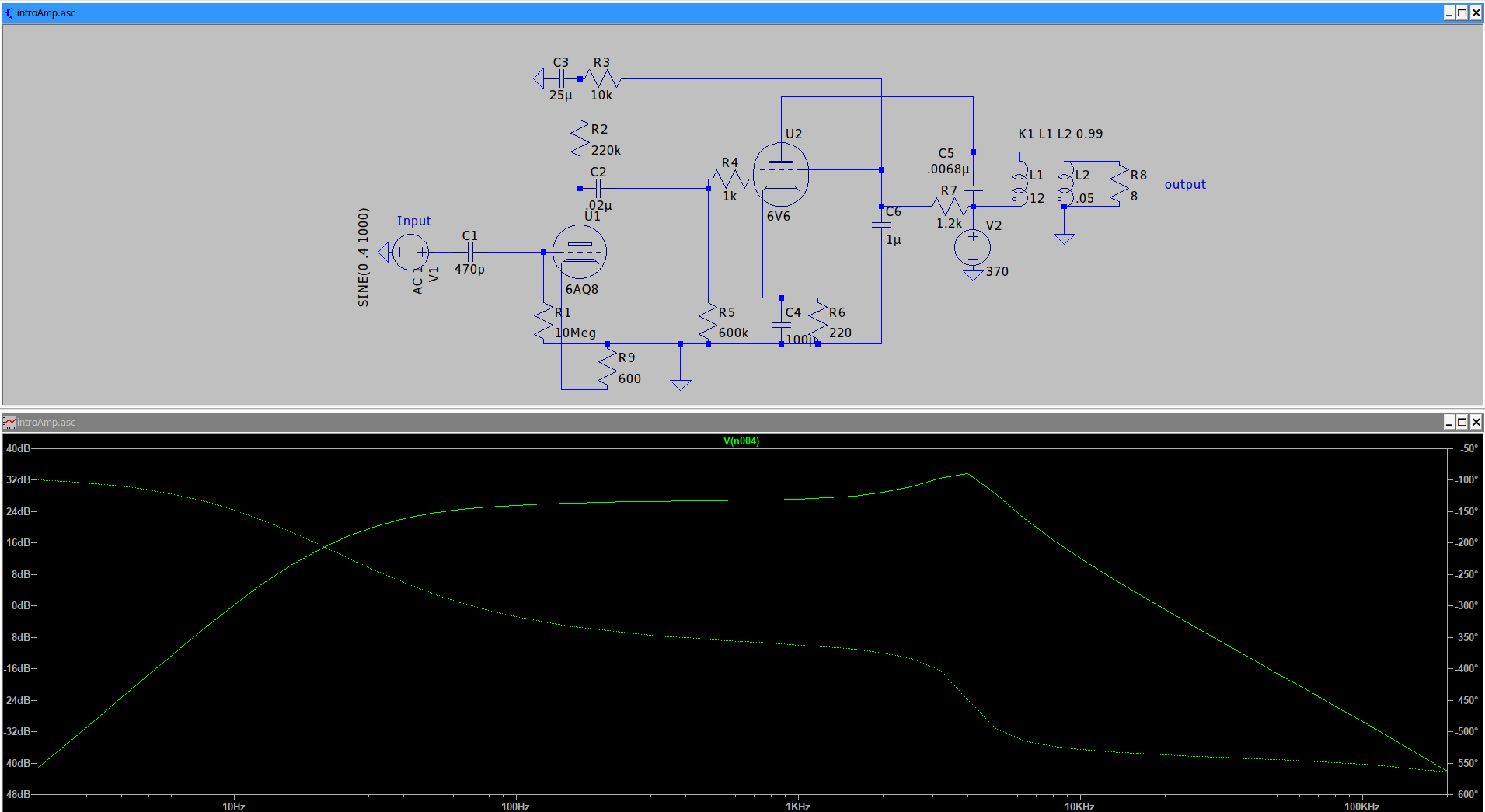
I tuned a few values and introduced a little more complexity to get my final circuit design as such, shown with the frequency response curve of the output.
-
There is quite a bit going on here if you are unfamiliar with these kinds of circuits, but if you have seen a few, this sort of looks
about as basic as you can get. The basic idea is that we give signal to the control grid of the first tube, represented by the
circles with dotted and solid lines in them. The two solid lines represent two plates that create an electric potential. Not shown in the top-down perspective is
a fillament that boils of electrons. Naturally, the electrons will be accelerated by the created electric potential, but the control grid(s) allow or
disallow the electrons to flow based on the signal it receives. The basic schematic here is a two tube design, where the first 6AV6 (depicted as 6AQ8)
operates at a lower potential difference, which amplifies the signal enough to drive the full-scale potential difference found in the power stage, or the
6AQ5 (depicted as 6V6.) The remainder of the parts are merely to act as an elaborate serise of ac and dc filters that allow these potential
differences to be maintained while passing around the ac signal, and avoiding sharp spikes that might come from unsteady power or signal. One of the nifty things about
modern technology is that we can simulate the frequency response curve, pictured on the bottom of the picture above. We see a relatively steady power increases
from about 60hz to about 8khz, and a steady dropoff after that. This is not ideal, because lots of the useful frequency is contained above this threshold. Another
constraint here is that due to the low-power output transformer, the coupled inductors on the right, and of the power tube used, we only get a theoretical 5w of power from
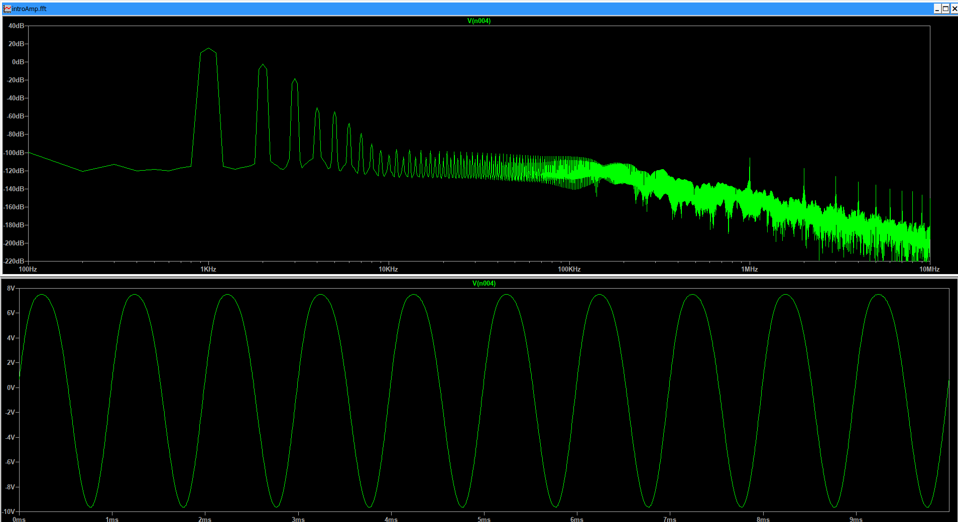
this design, but in practice, we get maybe half of that. Another cool plot we may look at is the Fourier serise of a fundamental frequency. As seen here.
-
Here I input a single perfect 1Khz signal into the amplifier, and we look at the output spectrum across the frequency band. Physicists and musicians out there may be interested
in the 2Khz frequency peak immediately to the right of the fundamental. This is the second harmonic, a very important tone in the sound profiles we hear day-to-day. Likewise, we
step through each doubling frequency at a lower average intensity each time. The even number peaks, so 2,4,6,etc. are known as the even harmonics, and the odd peaks 3,5,etc,
are the odd harmonics. Generally one wants to minimize the total noise, or the region not taken up by harmonics, as well as the relative size of the
harmonics compared to the fundamental tone. This is a stat known as total harmonic dissonance, or THD. While these are both valid metrics, some folks really like the sound of the even order harmonics,
so if given the choice, it is often favorable to have stronger even harmonics than odd, and some people will even try to re-inject some even harmonics on very clean builds. The behavior
we see in this simulation is pretty mediocre. We have a low noise floor, which is nice, but the harmonics make up a significant portion of the signal. This perhaps looks a bit more dire than
it really is, because dB is a log scale, but around 4% of our final signal is just made of the harmonic serise instead of the fundamental. This is considered rather poor performance, but given
the strong presence of the even harmonics, perhaps this is alright.
-
I learned quite a bit about the build process along the way, but most of all, I was quite annoyed with the fundamental limitations from before, causing me to put some time into a complete redesign
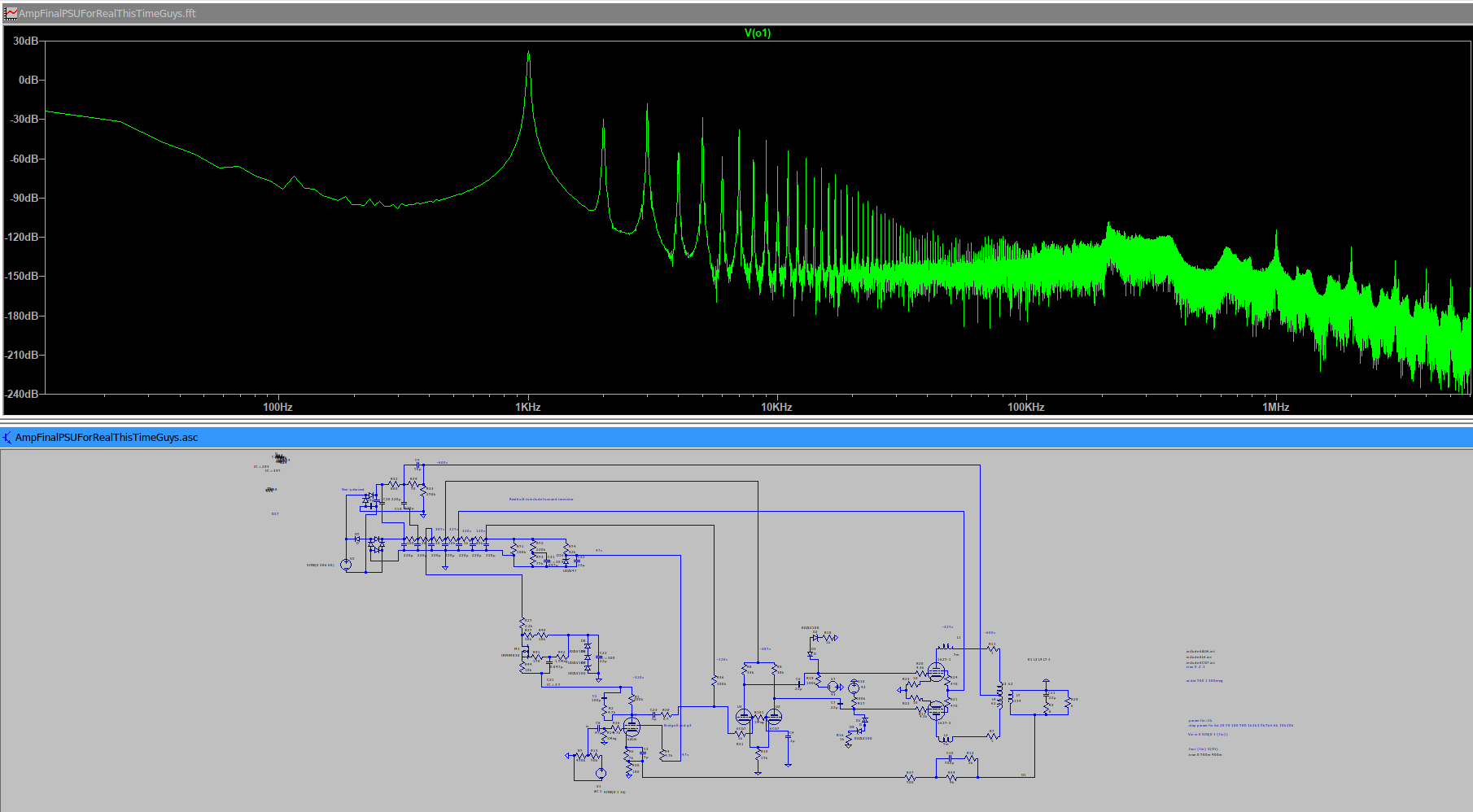
of a brand-new circuit. Behold, in all its glory my next creation:
-
There are a couple really cool changes here. Most having to do with clever tricks to reduce harmonics. Firstly, this circuit is in whats called Push-Pull topology, instead of
Single Ended like the first one. While this requires an additional tube, and a phase inverter, we gain more than double the output power, and we get a built-in harmonic suppressor.
Unfortunately, this suppression only works well to eliminate the even harmonics, so the utility is mixed. The double pentode in the middle is called a Long Tail Pair phase inverter.
We get the advantage of not only phase inversion, but also an additional stage of gain, which you will see is important next.
Extra gain headroom lets us do one of two things. Either, we can output a louder signal, or we can implement feedback. The output signal is rarely limited by tubes now-a-day, but by
how large of a transformer you want to pay for on the output stage. Given I am going to work with a 25w transformer, we have lots and lots of extra gain.
Feedback is a clever process where we take a portion of the signal where it is perfectly out of phase with an earlier part of the signal branch, and we re-inject a small portion to cancel
out some of the earlier signal. This obviously removes some of the output, but it turns out that this disproportionately removes upper harmonics. If we make lots of extra gain before
the transformer, we can cash in some of that gain for a cleaner signal.
While this build is currently just on paper, the simulations are incredibly promising. I have the 6L6 tubes in place of the real 1625's because no tube library that I could
find for ltSpice has the 1625 modeled. The 6CG7 is also just one tube that contains two triodes, and the 6AU6 I picked out is a more robust military spec with some extra letters
that essentially amount to the same tube. All this means that this circuit can be had for extremely cheap, despite the
complexity present. I might be able to make this build with a total B.O.M including PSU circuitry and OT in the ~$250 range. Perhaps one day when I have some spending money...